Simplify power monitoring and avoid some of the outages that can be caused by power issues, using data from a rack power distribution unit (rPDU), and more.
Have you ever lost power to a server? Did it ever reboot on its own? Wouldn’t it be nice to prevent power outage to IT devices? If this is something you’ve experienced in the past, there are ways to simplify power monitoring and avoid some of the outages that can be caused by power issues. This article will focus on using power consumption data from a rack power distribution unit (rPDU) and how to simplify the process.
Many things can cause power problems. Have you ever experienced an outage due to a breaker tripping at home? I remember plugging in a fan one hot summer that tripped a breaker, shutting off the lights and my computer. This problem was quickly resolved. I just had to reset the breaker in the electrical panel and use a long extension cable to plug the fan into a socket in another room.
Imagine that happening in your IT infrastructure. It’s a nightmare for many reasons and remediation isn’t as simple as at home. Data centers are much larger, far away, and there are more breakers in every room of data centers.
Monitoring an electrical power system for a data center can be difficult but it doesn’t have to be. Some say it’s part science and part magic. It is hard to explain because physics is involved when discussing electricity. I’ll leave out the physics and logically describe how to gain the benefits of monitoring the power system. There are three main benefits that can be achieved:
Improved uptime
Reduced power expense
Increased efficiency by supporting more IT equipment
I will focus on improving uptime since is the foundation before other benefits can be realized. After all, your on-premise data center houses the most critical application, so everything should be done to prevent outages.
Electrical Power System Overview
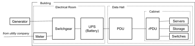
To increase uptime for the IT devices, some knowledge of the power system is required. Here is a simplistic, non-redundant overview:
All of the electrical power equipment must function properly in order for the IT devices to perform and deliver the always-connected, available anywhere applications to the digital world. Everything is built-in redundancy so the actual diagram should be much more complicated.
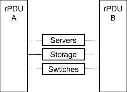
As you can see, IT devices get their power from the rack power distribution unit (rPDU). In the simplest form, they are larger versions of the power strip that you have on your desk. It connects to the power source and provides many outlets for the IT devices. They need to provide power and protect the IT devices. Modern IT devices require multiple power connections as they are power-hungry and also to provide redundancy within the device. As such, there are typically two to four rPDUs that feed power to IT devices. Two rPDUs are used for redundancy, just in case something in one power system fails.
The two main power attributes for our purpose are 1) “current” expressed in amperage (A or amp), and 2) “voltage” expressed using the same term, voltage (V or volt).
Provisioning Recommendations
Now that we have a basic understanding of how IT devices are connected to the power system, we have to discuss a little bit of math. There are three rules to follow when provisioning the rPDUs:
Only provision to 50% maximum so that one unit can take the full load when its redundant pair fails
Reserve 20% of its capacity to accommodate usage spike, e.g. during initial power-up (increase in fan noise is a good indicator)
Never connect to open outlet within the rPDU without knowing the actual power usage load (which is what happened when I plugged in the fan in the introduction)
Amperage
With the rules above, only 40% of rPDU capacity should be provisioned realistically. Power current measured in amperage is the attribute used most when provisioning the power system. For example, with a 30 Amp rPDU, it should be handling less than 12 Amp most of the time.
Many rPDUs further segment within the unit. Each segment is commonly known as Branch Circuit. Typically, there are two to three branch circuits within a unit. Each branch circuit also includes a breaker to protect one circuit from another. These breakers are rated at 16 Amp (which is 80% of 20 Amp). This rating matches the capability of the C-13 and C-19 connectors that many IT devices use.
Recommendation #1 – Monitor Current at the Branch Circuit Level
Branch circuit breakers will engage (trip) under two conditions:
A power surge in the system caused by any of the connected devices
Overconsumption when connected IT devices require more than what rPDU can handle
To avoid breakers tripping, I recommend these alert threshold settings power current:
Warning at greater than 30%
Error at greater than 35%
Critical at greater than 38%
When you get the warning alert, you should keep a close eye on it to make sure that the power consumption is not increasing over time. When you get the critical alert, consider re-provisioning or moving some of the IT devices off that branch circuit. Having historical data can assist in identifying where to move it.
Voltage
So far we mainly discussed the power current attribute. Another important attribute is the power voltage measured in voltage (V). Power current and voltage work together but they behave differently. Most IT devices use power supplies that have their own performance requirements, expressed both in the amperage and voltage. When under-delivered, the power supply units cannot provide sufficient power to components within the IT devices which can cause an outage.
NOTE: Many IT devices will report the power consumption. Make sure to look for input (not output) of their power supply to compare to power measurements from the rPDU.
Recommendation #2 – Monitor Voltage
Power voltage does not vary significantly within the rPDU. Monitoring voltage and comparing it to the requirements of the power supply is critical. Most IT device power supplies will have a range of 208V to 240V. Unlike amperage, the voltage should be monitored so it does not go below the minimum requirement.
To avoid issues with the devices power supply, I recommend these alert threshold settings for power voltage:
Warning at less than minimum voltage requirement (e.g. 210V)
Error at less than 5V below the minimum voltage requirement (e.g. 205V)
Critical at less than 10V below the minimum voltage requirement (e.g. 200V)
The power supply and its requirement from the vendor behave differently, let’s call this sensitivity. The sensitivity of the actual voltage that might cause the power supply to fail will vary between units and models but this is a good starting point.
If any of the alerts are triggered, keep an eye on it, and if it occurs regularly, contact an electrician to resolve the issue. Low voltage is commonly a problem with the source where rPDUs get their power. Typically, a floor-standing PDU is a source. It handles higher power so an electrician is needed to investigate the issue.
Simple Network Management Protocol (SNMP)
Many rPDUs with monitoring capabilities support SNMP, which is great news. The bad news is that ObjectID needed to implement my recommendations is not standardized, so it requires a little investigation to determine which OID to use.
Here is a sample SNMP OIDs for some of the vendors:
Vendor
Branch Circuit Current
Voltage
APC (Schneider Electric)
.1.3.6.1.4.1.318.1.1.15.4.2.3.1.5.a a = xPDUBranchBreakerTableIndex
.1.3.6.1.4.1.318.1.1.15.3.1.4.1.2.a a = xPDUMainInputVoltagePhaseIndex
Eaton
.1.3.6.1.4.1.534.6.6.7.5.4.1.3.a.b a = strappingIndex b = groupIndex
.1.3.6.1.4.1.534.6.6.7.5.3.1.3.a.b a = strappingIndex b = groupIndex
Geist (Vertiv)
.1.3.6.1.4.1.21239.5.2.3.3.1.4.a a = breakerindex
.1.3.6.1.4.1.21239.5.2.3.3.1.8.a a = breakerindex
Raritan (Legrand)
.1.3.6.1.4.1.13742.6.5.3.3.1.a.b.1 a = pudid b = breakerid
.1.3.6.1.4.1.13742.6.5.3.3.1.a.b.4 a = pudid b = breakerid
Server Technology
.1.3.6.1.4.1.1718.3.2.7.1.7.a.b.c a = towerIndex b = infeedIndex c = branchIndex
.1.3.6.1.4.1.1718.3.2.2.1.11.a.b a = towerIndex b = infeedIndex
NOTE: refer to vendor specific Management Information Base (MIB) for details
Benefits of Using LogicMonitor
LogicMonitor can simplify monitoring electrical power system. With automations and deeper insights into power consumption data, taking the proper action at the right time can help in avoiding outages related to electrical power issues. Here are some feature highlights that have a direct impact on power monitoring:
Automatically monitor power consumption
Active Discovery can automatically detect rPDUs with monitoring capabilities
PropertySource can automatically identify the type of rPDU and differentiate between all the variants used, e.g. single phase vs 3-phase
DataSource can automatically collect power consumption and apply alert thresholds
Take actions based on deeper insight
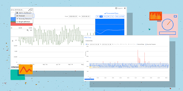
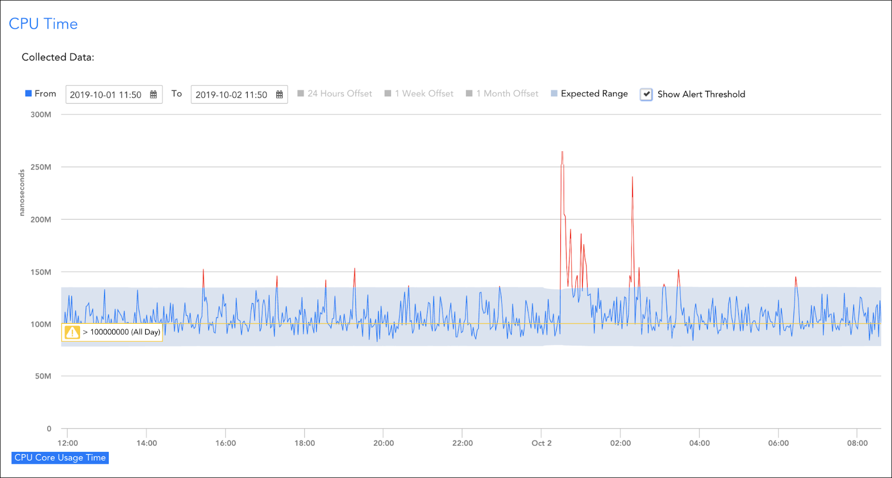
Dynamic Threshold will learn each units normal operating consumption and alerts when reading shows outside the benchmarked band (gray bar below) even when consumption within the rPDU’s capability
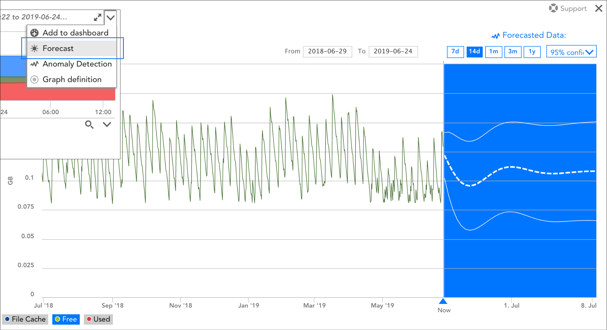
Forecasting will provide early visibility to a potential risk of reaching the ceiling of the rPDU capacity
As you can see, preventing potential outage caused by the electrical power system can be easily implemented purposefully using LogicMonitor. We make it simple to add rPDUs as a monitored resource and apply alerts and analyze collected data. As the saying goes, you set it and forget it. If you are interested in learning more about LogicMonitor’s capabilities, connect with your customer success manager or attend a weekly demo to see LogicMonitor in action.
Disclaimer: The views expressed on this blog are those of the author and do not necessarily reflect the views of LogicMonitor or its affiliates.