
Topology Map Creation
Last updated - 08 June, 2026
Topology Maps in LogicMonitor visualize relationships between monitored resources and their dependencies. Use topology maps to explore connectivity, understand how resources interact, and investigate issues across your monitored environment.
Requirements for Creating Topology Map
To create a topology map, you need the following:
- Resources must be assigned external resource IDs (ERIs).
- The host property
predef.externalResourceIDmust contain a value.
Creating Topology Map
To create a topology map, complete the following steps:
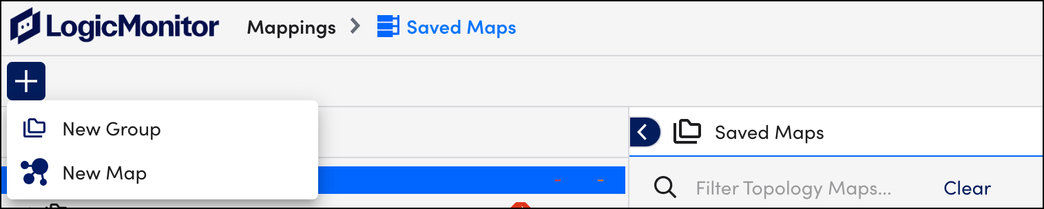
- In LogicMonitor, navigate to Mapping > Saved Maps > Add
- Select New Map.
- In the Add Resources dialog box, select the “Group” and the “Resource name” to add the required resource. You can also add multiple resources.Note: You can only add the resources that are assigned with external resource IDs (ERIs).
To verify if the resource has an ERI, check if the resource has the value for the host propertypredef.externalResourceID.Note: If the resources are inaccurately displayed on your topology map, see the troubleshooting section of the Topology Mapping Overview. - (Optional) Enter the instance name to add instances.
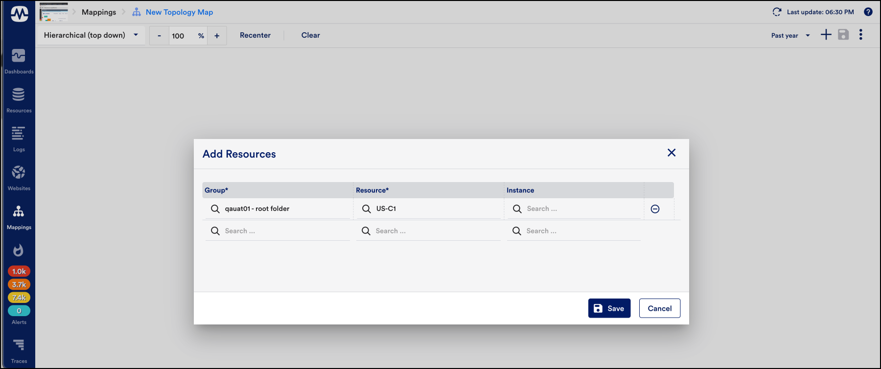
- Select Save.
- Select the newly added resource and an Actions drop-down button is displayed.
- Select Edges, to filter relationships between resources.
Each added relationship consists of a second vertex, connected to the first vertex by an edge.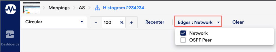
- From the Actions drop-down menu, select Unpin, to unpin a resource. When you select Unpin, the selected resources will disappear.Note: You can expand any vertex whenever required. Also, you can traverse relationships across your network environment indefinitely.
- (Optional) From the Actions drop-down menu, select Connections, to view the incoming or outgoing relationships between resources.
- From the Layout field’s dropdown menu, select an organizing structure for the topology map’s layout:
- Hierarchical (top-down): This is the default layout. In this layout, vertices are organized in a top-down tree-like structure.
- Hierarchical (left to right): The horizontal layout is essentially the hierarchical layout rotated ninety degrees counter-clockwise. Relationships flow left to right.
- Dynamic: This is a force-directed layout algorithm. Vertices repulse each other and edges act as “springs” to pull them together.
- Radial: The radial layout positions vertices in a circle originating from a starting center vertex.
- Circular: The circular layout positions the groups’ related subsets of the nodes into circular patterns.
- Hierarchical (top-down): This is the default layout. In this layout, vertices are organized in a top-down tree-like structure.
- Select Recenter to set the map in the center.
- Select – or + on the percentage zoom setting to zoom in gradual increments.
- Select Clear to clear the canvas when viewing existing topology maps or building new ones. It does not permanently delete a saved map.
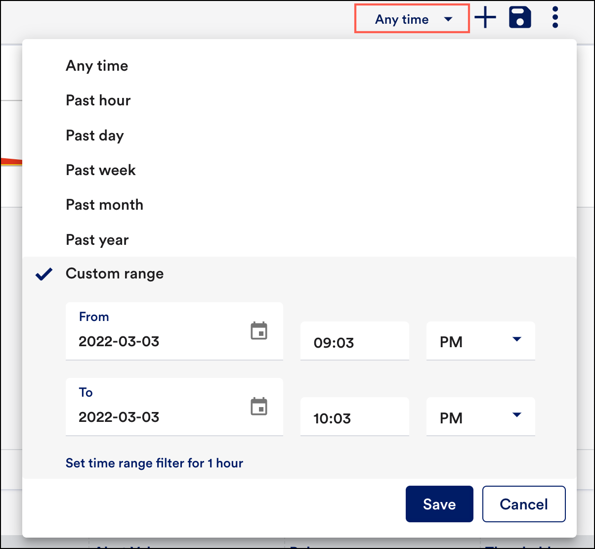
- Select the Time Series drop-down, to select the time range for which you want to check the status of the monitored resources.Note: The Time series filter is applied only to the alerts present on all nodes within the map.
- From the Time Series option, select Custom range to customize the time range. Once you enter the required time range, select Save.
- Select Save to save the map. However, several configurations must be completed upon first save. For more information, see Saving Topology Maps.
