Topology Mapping Overview
Last updated on 21 August, 2024FEATURE AVAILABILITY: LogicMonitor Pro and Enterprise
Topology mapping is the visual representation of relationships among elements within a communications network. Topology maps can represent the physical location of network components, generally referred to as layer 1 mapping, or they can represent the transmission relationships among corresponding elements, referred to as layer 2 mapping, or they can represent the routing and traffic control aspects of a multi-node network, referred to as layer 3 mapping.
LogicMonitor’s topology mapping capabilities are focused on layer 2 and layer 3 mappings. Specifically, the LogicMonitor platform leverages Link Layer Discovery Protocol (LLDP), Cisco Discovery Protocol (CDP), Border Gateway Protocol (BGP), Open Shortest Path First (OSPF), and Enhanced Interior Gateway Routing Protocol (EIGRP) to dynamically generate network topology maps that show how data flows among the many resources (switches, hosts, firewalls, routers, and other network components) in your environment.
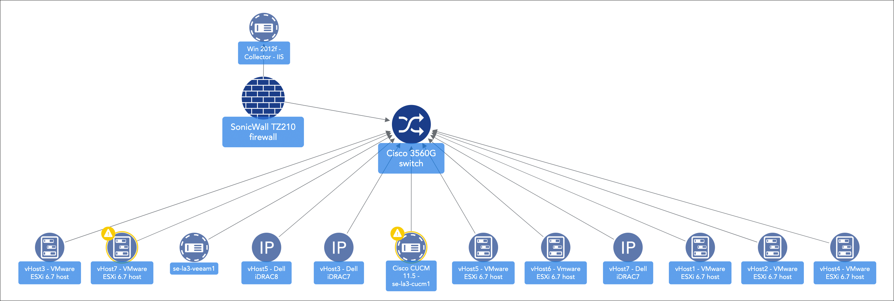
LogicMonitor takes an additive approach to generate topology maps. This approach initially shows only the relationships that are most relevant for the current task at hand but can be expanded outward. For more information on creating, saving, and adding topology maps to your dashboards, see Mapping Page.
The context that LogicMonitor’s topology mapping provides can be very beneficial to your monitoring operations, providing you with the ability to:
- Visualize and navigate resources based on topology relationships
- Quickly determine the root cause of an incident that is impacting dependent resources (and optionally suppress alert notification routing for those alerts determined to be dependent on the originating alert). See Enabling Root Cause Analysis for more information.
- Troubleshoot alerts within your infrastructure on a topology map
- Generate topology maps based on alerts to streamline your troubleshooting workflow
- Discover and map relationships between resources
- Save relevant and frequently-used topology maps for monitoring continuity
Getting Started
In order to enable topology mapping, you’ll need to ensure all necessary LogicModules are imported and up to date, as outlined next:
- From the LogicMonitor repository, import all TopologySources. As discussed in the TopologySources section of this article, TopologySources are a type of LogicModule created specifically for topology mapping.
- From the LogicMonitor repository, import all relevant PropertySources. These include:
- addERI_*. All PropertySources prefixed with “addERI_” (e.g. addERI_Cisco, addERI_Vcenter, and so on).
- addCategory_TopoSwitch. This PropertySource helps LogicMonitor identify those resources that are fit for network TopologySources.
- For some types of resources, notably VMware and Kubernetes (there are others as well), DataSources carry some instructions for topology mapping. For this reason, it is best practice to ensure that all DataSources in use on your platform are up to date. Important: Importing DataSource updates has the potential to override customizations you’ve made to your modules and, as such, we recommend you carefully assess updates (via the diff viewer) prior to import.
Once you’ve completed these steps, your newly-imported TopologySources will automatically start connecting ERI keys and forming relationships among all resources currently monitored by LogicMonitor in order to dynamically generate topology maps. Topology maps can be created, saved, and added to dashboards from the Mapping page, as discussed in Mapping Page.
Note:
- By default, only users assigned the default administrator and manager roles will initially be able to render topology maps. For more information on the permissions available for topology mapping, see the Role-based Access Control for Topology Mapping Features section of this support article.
- You can add topology mapping capabilities for selenium synthetics checks. For more information on synthetics checks, see LM Synthetics Overview.
Components of Topology Mapping
There are several primary components that contribute to the generation of a topology map:
- Vertices
- External Resource IDs (ERIs) and External Resource Types (ERTs)
- Connections
- TopologySources
Vertices
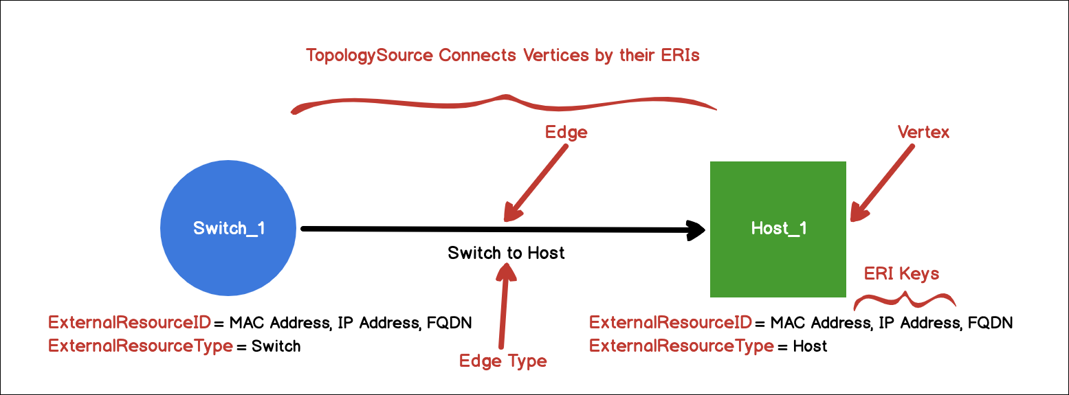
Vertices are logical objects inside LogicMonitor that represent one or more resources within topology. A vertex is identified by the external resource ID (ERI) and external resource type (ERT) that is assigned to the underlying resource being represented by the vertex.
External Resource IDs (ERIs) and External Resource Types (ERTs)
As discussed in the following sections, ERIs and ERTs are properties set on devices, instances, and services (collectively referred to as resources on the LogicMonitor platform) that allow resources to be recognized for inclusion in topology maps. Both the ERI and ERT for a resource are defined by either a PropertySource (for device-level ERI properties) or a DataSource (for instance-level ERI properties).
ERIs
An ERI contains a set of keys that, in combination, serve to uniquely identify a resource. One ERI can consist of many keys (all keys are stored as CSVs within the ERI itself) and a key represents one of three types of identifiers:
- Media access control (MAC) address
- Internet protocol (IP) addresses
- Fully qualified domain names (FQDNs)
ERI Priority
It is possible for more than one PropertySource or DataSource to generate ERI keys for a resource or instance. When this happens, LogicMonitor uses a confidence algorithm to determine which ERI takes precedence.
All generated ERIs per category, along with the individual keys that make up each ERI, now display on the Info tab (available from the Resources page) to provide insight into full ERI (stored as the value of the predef.externalresourceid property) generation based on the priority determination. The ERI values with the highest assigned priority number (i.e. the ERIs at the top of the list) are the ones that take precedence and are used to generate the full ERI used for mapping the to/from relationships via the TopologySources.
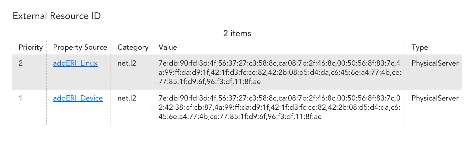
The category defines the type of device or technology for which the ERI keys were generated. The rules for how category and priority interact for the full ERI generation are as follows:
- Within the same category, only ERI value(s) with the highest priority will be preserved; values in the same category that share the same priority will be merged
- Values from different categories will be put together (comma separated) to make the full ERI
ERTs
While an ERI specifies the unique identifier of a resource/vertex, the external resource type (ERT) specifies its type. The value assigned to an ERT determines the technology-specific icon used to represent the resource/vertex on rendered topology maps.
Connections
In Topology, a connection represents the relationships between two vertices on a topology map. Any given vertex can have multiple connections. In most scenarios, a vertex will have at least two connections: one that is outgoing and one that is incoming.
An outgoing connection indicates that the respective vertex has relationships that are emanating outward. For example, imagine that you want to view a Cisco switch’s CDP neighbors. To do this, you would select the outgoing connection labeled “NETWORK” on the topology map and all CDP neighbors would appear. Conversely, an incoming connection means that the respective vertex has been discovered by a TopologySource applied to a different resource. In the scenario provided, all of the vertices that were initially discovered by the vertex with the outgoing connection “NETWORK” would also have incoming connections named “NETWORK.”
The name of the connection that connects two resources is the connection type. If we continue with the “NETWORK” example, “NETWORK” is the connection type. For every connection, there can only be one connection type. There cannot be multiple names for the same connection between two resources.
The connection and the connection type are both defined in the TopologySource. In the JSON payload produced by the TopologySource script, the connection type is represented as “Type.”
TopologySources
TopologySources are a type of LogicModule devoted specifically to topology mapping and take a form similar to scripted DataSources. TopologySources use ERIs to define the connections between vertices. The successful output of a TopologySource is a JSON object consisting of vertices and connections. See TopologySource Overview.
For most networking topology, TopologySources are leveraging layer 2 and layer 3 discovery protocols to gather information about VLANs. This information is contained in certain OIDs, WMI classes, and API calls. For VMware, TopologySources are accessing the vCenter API to gather relationship information and leverage the VMMoRefIds.
Note: In rare instances, TopologySources can execute “successfully,” but no resulting relationships display in the mapping UI. This is because TopologySources don’t technically need ERIs defined on AppliedTo resources in order to execute successfully. If you experience this, it is likely that you have not imported all the necessary LogicModules (such as PropertySources and DataSources) responsible for assigning ERIs to the resources currently monitored by LogicMonitor. See the Getting Started section of this support article for a detailed listing of the requirements.
An Example Scenario to Tie It All Together
The following example scenario was created to help you visualize how TopologySources use ERIs to define connections between resources and render topology maps.
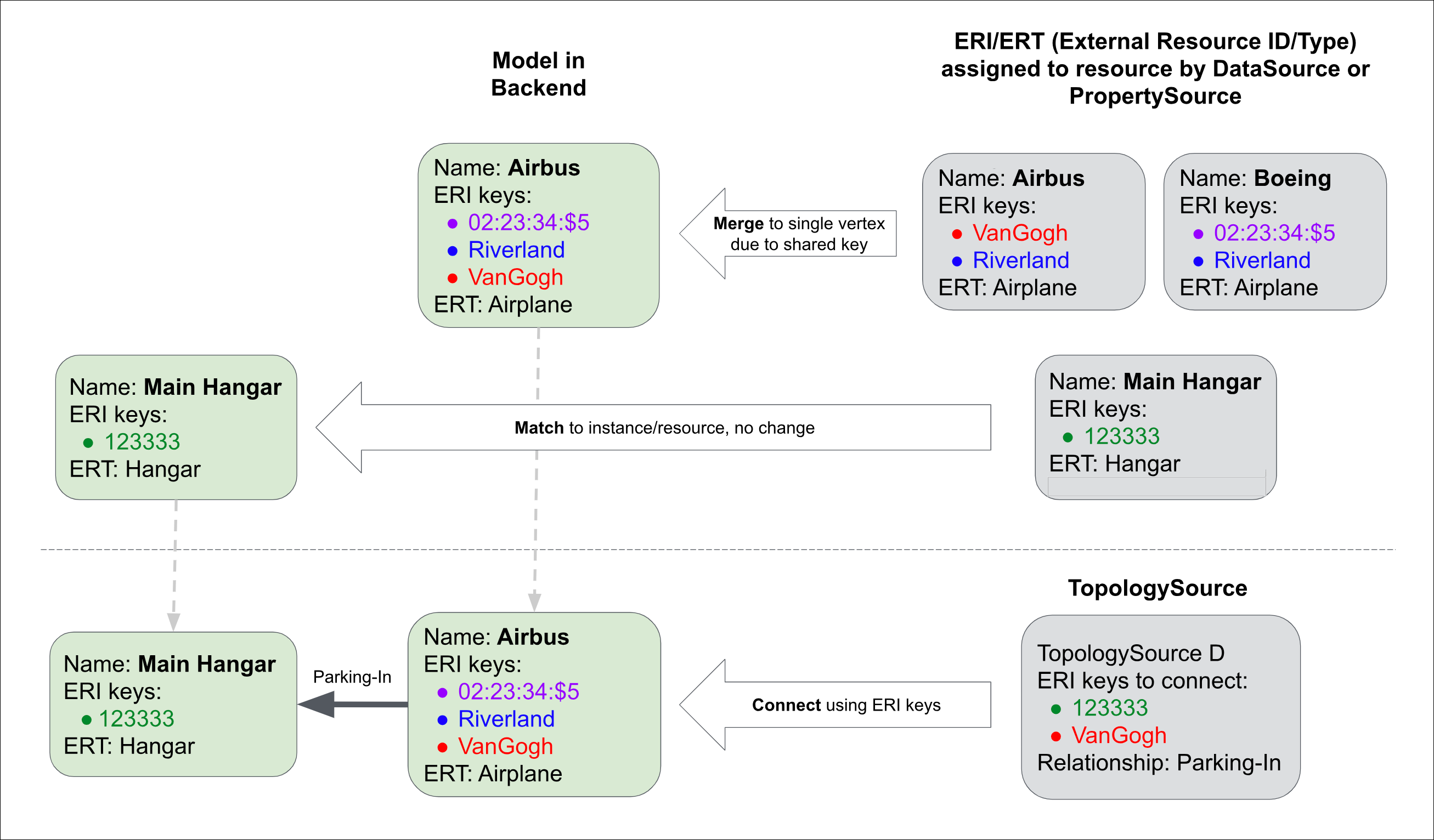
In the diagram above, we are illustrating how a TopologySource orchestrates the relationship between an airplane and the hanger that it parks in. Let’s walk through the diagram counter-clockwise:
- Starting with the TopologySource in the bottom right of the diagram, we see that its “recipe” is to connect resources whose ERIs contain the key “123333” with resources whose ERIs contain the key “VanGogh.” Once these resources are connected, an connection (relationship) is formed with the connection type (i.e. name) of “Parking-In.”
- Immediately above the TopologySource, three resources have been identified as having ERIs containing the keys referenced by the TopologySource: Main Hangar, Boeing, and Airbus. Two of these resources have an external resource type (ERT) of “Airplane” and one has an ERT of “Hangar.” Three different DataSources assigned these ERI/ERTs respectively.
- As we move to the left, we see how the topology map is modeled on the backend. Notice in the upper left that there is only one vertex representing the two airplane resources. As discussed in the ERI Merging section of this support article, LogicMonitor looks for duplicate ERI keys when rendering topology maps; if the same ERI key is assigned to two or more resources (as is the case here, both share the ERI key “Riverland”) they are merged into a single vertex. In the event that a vertex represents merged resources, its display name will be that of the resource with the smallest ERI and its ERT will be the one that comes first alphabetically.
- Continuing on, the Main Hangar resource is modeled, without change, as a vertex.
- And, finally, the end result of the diagram is the connection between the Airbus and its Main Hangar, defined by a connection named “Parking-In.”
Extrapolating Example to VMware
Next, let’s extrapolate from the simplistic, non-real-world example highlighted previously to one that is likely more pertinent to your LogicMonitor operations: mapping topology among VMware components (e.g. vCSA → cluster → host → VM → etc.). In the case of VMware, DataSources will assign both the managed object reference ID (MoRef) and MAC address as resource ERI keys.
For example, the result of the ERI script would look something similar to predef.externalresourceid = 10.41.16.7–host-1981, 00:21:28:6b:09:dc, where the host ID is appended to the vCenter’s IPv4 address and the MAC address is also assigned to the resource as an ERI key. Assigning the MoRef as an ERI key allows you to leverage the vCenter API to define multiple relationships; the MAC address is used to tie the host back into the network and show the switch to which it is connected.
The TopologySource would look to connect ERI keys assigned to virtual machines, hypervisors, cluster, vCSAs, and so on. If LogicMonitor detected any duplicate ERI keys among these components (e.g. you’re monitoring a VM via vCenter, and also via SNMP as a separate resource), they would be merged into a single vertex when rendered by a topology map.
Role-based Access Control for Topology Mapping Features
Topology mapping, like many other features in the LogicMonitor platform, supports role-based access control. By default, only users assigned the default administrator and manager roles will be able to render topology maps and access the full range of topology mapping features (users assigned the readonly role will see the Mapping page and any saved maps). As discussed in Roles, roles can be created/updated to allow for full or limited access to topology mapping features.
Creating Custom Topology Mapping Relationships
For the vast majority of users, there will be no need to create custom TopologySources or manually assign ERIs and ERTs, assuming all relevant files have been imported. Topology is automatically discovered and topology maps are dynamically generated.
However, similar to DataSources, the LogicMonitor platform does expose the ability to create new (or edit existing) TopologySources. Similarly, DataSources and/or PropertySources can be created or modified to assign custom ERIs and ERTs. Because this is an involved process, requiring careful consideration in ensuring unique ERIs, as well as script building, we recommend you reach out to our support team for guidance.
Troubleshooting Inaccurate Resource Display on Topology Maps
When rendering topology maps, LogicMonitor looks for duplicate ERI keys among resources. If the same ERI key is assigned to two or more resources, these resources are merged into a single vertex and its display name will be that of the resource with the smallest ERI and its ERT will be the one that comes first alphabetically.
LogicMonitor merges resources in this manner to ensure that the same resource isn’t represented multiple times on a topology map. Because LogicMonitor has the flexibility to monitor a resource multiple times, often with different technology domains (e.g. SNMP/WMI or vCenter for a VM), there needs to be a way to represent that resource cohesively.
However, there are times when ERI merging causes unexpected results including the wrong resources displayed on topology maps or devices not being mapped at all. To address these ERI key merge issues, LogicMonitor offers two properties:
- topo.namespace
- topo.blacklist
For instructions on assigning properties to resources, see Resource and Instance Properties.
topo.namespace Property
The topo.namespace property should be your first line of defense. This property addresses merge issues across resources in different groups, such as customer groups. An existing property is assigned to the topo.namespace property and this namespace value is then prepended to all ERI keys for the resource.
This will create unique keys for those resources in cases where keys that have been replicated across environments are causing ERI merge issues. This property is especially relevant for topology mapping in MSP environments.
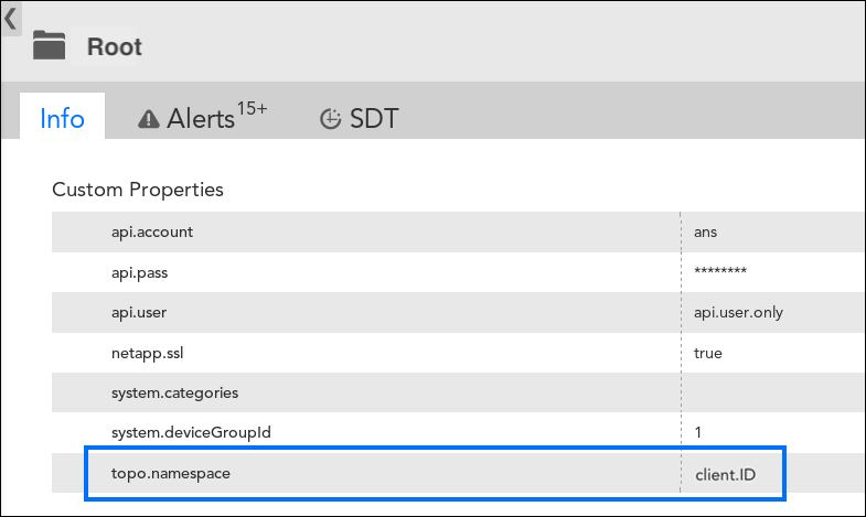
In most cases, you’ll want to define the topo.namespace property at the root folder level.
topo.blacklist Property
The topo.blacklist property bans certain ERI keys from consideration. For example, if a MAC address is duplicated across multiple resources and causes an incorrect merge, you can enter that address as a value of the topo.blacklist property to exclude it from use in ERI key generation.
When applicable, use the topo.namespace property to solve the issue of incorrect merging before using the topo.blacklist property. But for those issues that can only be addressed via ERI exclusion, set this property at the root, group, or resource level (it is recommended to set it at the deepest level possible).
Note: If the topo.namespace property is being used in conjunction with the topo.blacklist property, be sure that values assigned to the topo.blacklist property does not include the namespace prefix assigned by the topo.namespace property.
If you use the topo.blacklist property locally, we ask that you additionally reach out to support to report your use case. Not only will this allow us to assess the effectiveness of this property in your environment, but it will also allow us to determine if your use case may apply to others and, therefore, be formally addressed by the product.
Debug Commands for Duplicate ERI Keys
Two commands are available from the Collector Debug Facility that allows you to debug issues related to the existence of duplicate ERI keys:
- !erimergelist [threshold=xxx] – This command lists all ERI values that appear across resources/instances (or those that meet a designated threshold if specified)
- !erimergedetail – This command lists all the resources/instances bound to an ERI value
FAQs
Q: My TopologySource is reporting connections, but the UI is not reflecting the same.
A: Make sure an ERI is applied and is hitting the correct resources. TopologySources report relationships independent of ERI scripts which may confuse users into thinking that topology should be available on the UI as well.
Q: My TopologySources are not executing successfully even though I have the proper credentials set.
A: For SNMP-based TopologySources, it has been observed that some OIDS cannot be queried for on a device. Example: Querying a Juniper Switch for CDP (Cisco Discovery Protocol).
Q: My network topology does not relate to how my network actually is laid out.
A: Make sure that all resources that are in the network path are being monitored by LogicMonitor, and that they have the proper credentials (e.g. snmp, wmi, esx.user, and esx.pass) and protocols enabled.
Q: I am seeing a vertex with a different display name than what I was expecting.
A: This is likely due to a merging of resources as a result of one or more resources having the same ERI key. Learn more about ERI merging in the ERI Merging section of this support article.
Q: Do I need to add a map for each resource?
A: No. A single map can be modeled to contain any logical grouping of resources you see fit. This could be a customer site, a particular business unit, the supporting infrastructure a service runs on, and so on.
Q: Will the load generated by the TopologySource place excess strain on my Collectors?
A: Since we are gathering relationship data with protocols such as SNMP, WMI, API, etc., there is a necessary increase in the Collector load. However, since the data we are gathering is not metric data, the polling interval can be greatly reduced (e.g. >1 hour in some scenarios).